Hallo zusammen,
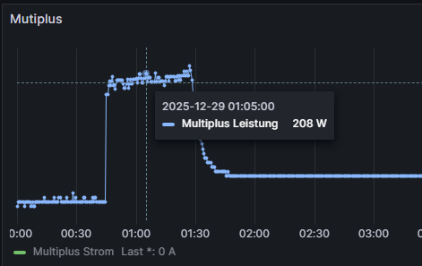
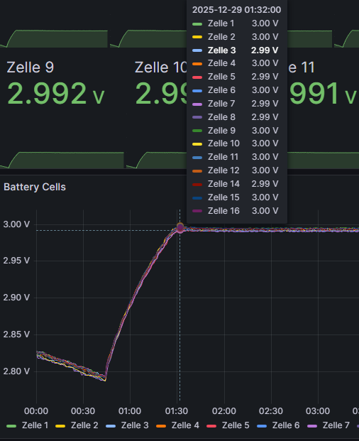
bei meinem alljährlichen Check ist mir folgendes Verhalten aufgefallen. Der Multiplus lädt über Nacht minimal die Zellen auf bis er ca. 3V bzw. 48V erreicht.
Setup:
MP2 5000 - VenusOS - JK BMS - dBUS Serialbattery
Venus uns Serialbattery laufen auf dem latest release.
Ich bin mit gerade unsicher, aber in dbus Serialbattery finde ich keine Config die bis 3V resp. 48V geht. Kann es sein, dass es mit einer Einstellung VeConfig zu tun hat?
In dBus Serialbattery config.ini hab ich folgende Werte hinterlegt.
Die Werte aus der config.default.ini habe ich auch zum ausklappen angehangen.
MIN_CELL_VOLTAGE = 2.700
MAX_CELL_VOLTAGE = 3.500
FLOAT_CELL_VOLTAGE = 3.4
SOC_RESET_AFTER_DAYS =15
VOLTAGE_DROP = 0.05
BMS_TYPE = Jkbms
POLL_INTERVAL = 2
Dbus Serialbattery Default Config
[DEFAULT]
; --------- Set logging level ---------
; ERROR: Only errors are logged
; WARNING: Errors and warnings are logged
; INFO: Errors, warnings, and info messages are logged
; DEBUG: Errors, warnings, info, and debug messages are logged
LOGGING = DEBUG
; --------- Battery Current Limits ---------
; +++ Limits apply to each individual battery/BMS. +++
; +++ If you have multiple batteries, you need a battery aggregator. +++
MAX_BATTERY_CHARGE_CURRENT = 50.0
MAX_BATTERY_DISCHARGE_CURRENT = 70.0
; --------- Cell Voltages ---------
; Description:
; Calculates the minimum and maximum battery voltage based on the number of cells and their voltage.
; ATTENTION: This does not prevent overcharging or overdischarging of individual cells.
; To prevent overcharging and overdischarging, use these features (enabled by default):
; - Charge Voltage Limitation (prevents overcharging)
; - Cell Voltage Current Limitation (prevents both overcharging and overdischarging)
;
; Example:
; 16 cells * 3.45 V/cell = 55.2 V max charge voltage
; 16 cells * 2.90 V/cell = 46.4 V min discharge voltage
;
; Minimum voltage (can NOT be seen as cut-off voltage)
; Used to:
; - Ensures that the charge voltage limit (CVL) does not fall below the threshold if calculated dynamically
; - Set SOC to 0%, if SOC_CALCULATION is enabled
MIN_CELL_VOLTAGE = 2.700
; Maximum voltage (can be seen as bulk/absorption voltage)
; Used to;
; - Set the maximum charge voltage limit (CVL).
; - Set SOC to 100%, if SOC_CALCULATION is enabled
MAX_CELL_VOLTAGE = 3.50
; Float voltage (can be seen as resting voltage)
; Used to:
; - Set the maximum charging voltage (CVL) after the battery is fully charged
FLOAT_CELL_VOLTAGE = 3.4
; --------- SoC Reset Voltage (must match BMS settings) ---------
; +++ This section is independent and unrelated to the "SoC calculation" section below. +++
; This is used to reset the SoC to 100% periodically to correct SoC drift.
; Description:
; Some BMS systems may need to reset the SoC to 100% periodically due to SoC drift.
; For example, JKBMS resets its internal SoC value if it reaches the upper voltage level.
; Using this method, the charging voltage can be raised regularly to achieve that.
; (Other BMS systems like Daly need an active overwriting of the SoC parameter. This happens each time
; when the charging mode changes from bulk/absorption to float and the cells are equalized. They do
; not need this feature here.)
; Specify the cell voltage at which the SoC should be reset to 100% by the BMS.
; - JKBMS: SoC is reset to 100% if one cell reaches the Over Voltage Protection (OVP) voltage.
; It is recommended to start with OVP voltage - 0.030 (see Example).
; - Increase (add) by 0.005 in steps if the system does not switch to float mode, even if
; the target voltage SOC_RESET_CELL_VOLTAGE * CELL_COUNT is reached.
; - Decrease (lower) by 0.005 in steps if the system hits the OVP too fast, before all
; cells could be balanced and the system goes into protection mode multiple times.
; Example:
; If OVP is 3.650, then start with 3.620 and increase/decrease by 0.005.
; Note:
; The value must be higher than the MAX_CELL_VOLTAGE.
; You also have to set CELL_VOLTAGES_WHILE_CHARGING accordingly if you set CCCM_CV_ENABLE to true,
; otherwise the charging current will be reduced to 0 before the target voltage is reached and the
; battery will never switch to float.
SOC_RESET_CELL_VOLTAGE = 3.51
; Specify after how many days the SoC reset voltage should be reached again.
; The timer is reset when the SoC reset voltage is reached.
; Leave empty if you don't want to use the SoC reset feature.
; Example:
; Value is set to 15
; day 1: SoC reset reached once
; day 16: SoC reset reached twice
; day 31: SoC reset not reached since it's very cloudy
; day 34: SoC reset reached since the sun came out
; day 49: SoC reset reached again, since last time it took 3 days to reach SoC reset voltage
SOC_RESET_AFTER_DAYS =15
; --------- SoC Calculation ---------
; +++ This section is independent and unrelated to the "SoC reset voltage" section above. +++
; Description:
; Calculate SoC in driver instead of using BMS reported SoC.
; Cannot be used with EXTERNAL_SENSOR_DBUS_PATH_SOC.
; True:
; Calculate SoC in driver.
; - Integrate current reported.
; - Set SoC to 100% when battery switches to float mode (requires CVCM_ENABLE to be enabled).
; - Set SoC to 0% if:
; * Lowest cell voltage <= MIN_CELL_VOLTAGE.
; * Battery is discharging for at least 300 seconds.
; False:
; Use SoC reported from BMS.
SOC_CALCULATION = True
; --------- Current correction ---------
; Correct the current reported by the BMS using a correction list.
; CURRENT_REPORTED_BY_BMS: List of current values reported by the BMS.
; CURRENT_MEASURED_BY_USER: List of current values measured by the user.
; If the lists are the same, this feature is disabled.
; Example to set small currents to zero:
; CURRENT_REPORTED_BY_BMS = -300, -0.5, 0.5, 300
; CURRENT_MEASURED_BY_USER = -300, 0.0, 0.0, 300
; Example to set zero current to a small current:
; CURRENT_REPORTED_BY_BMS = -300, -1, 0.0, 0.1, 1, 300
; CURRENT_MEASURED_BY_USER = -300, -1, -0.4, 0.0, 1, 300
CURRENT_REPORTED_BY_BMS = -300, 300
CURRENT_MEASURED_BY_USER = -300, 300
; --------- Bluetooth BMS ---------
; +++ Bluetooth connections may be unstable on some systems. +++
; +++ For a stable connection, use the serial connection. +++
; Description:
; Specify the Bluetooth BMS and its MAC address that you want to use. Leave empty to disable.
; Available Bluetooth BMS:
; Jkbms_Ble, LiTime_Ble, LltJbd_Ble
; Example for one BMS:
; BLUETOOTH_BMS = Jkbms_Ble C8:47:8C:00:00:00
; Example for multiple BMS:
; BLUETOOTH_BMS = Jkbms_Ble C8:47:8C:00:00:00, Jkbms_Ble C8:47:8C:00:00:11, Jkbms_Ble C8:47:8C:00:00:22
BLUETOOTH_BMS =
; Force to use polling instead of active callbacks.
; Setting to False/True may help with unstable Bluetooth connections.
; False: Use active callbacks, if supported by the BMS
; True: Use polling
BLUETOOTH_USE_POLLING = True
; Try to reset the BLE stack if the connection is lost or a crash is detected.
BLUETOOTH_FORCE_RESET_BLE_STACK = False
; --------- Bluetooth use USB ---------
; +++ Works only on Rabpery Pi devices. +++
; Description:
; Some users reported issues with the built-in Bluetooth module. You can try to fix it with a USB
; module. After changing this setting, reboot the GX device.
; The USB Bluetooth module must support BLE (Bluetooth version >= 4.0).
; Other Bluetooth devices such as Ruuvi tags have not been tested yet.
; False: Use the built-in Bluetooth module
; True: Disable the built-in Bluetooth module and use a USB module
BLUETOOTH_USE_USB = False
; --------- CAN BMS ---------
; Description:
; Specify the CAN port(s) where the BMS is connected. Leave empty to disable.
; Show available CAN ports with: canshow
; Available CAN BMS:
; Daly_Can, Jkbms_Can
; Example for one CAN port (Cerbo GX MK2, Ekrano GX):
; CAN_PORT = vecan0, vecan1
; Example for one CAN port (Cerbo GX, Raspberry Pi):
; CAN_PORT = can0
; Example for multiple CAN ports:
; CAN_PORT = can0, can8, can9
CAN_PORT =
; --------- Daisy Chain Configuration (Multiple BMS on one cable) ---------
; Description:
; Specify the battery addresses as hexadecimal numbers for which a BMS should be searched.
; If left empty, the driver will connect only to the default address specified in the driver.
; Check the documentation for more information:
; How to connect and prepare the battery/BMS | dbus-serialbattery
; Example:
; BATTERY_ADDRESSES = 0x01, 0x02, 0x03, 0x04
BATTERY_ADDRESSES =
; --------- BMS Disconnect Behavior ---------
; Description:
; Block charge and discharge when communication with the BMS is lost. If you are removing the
; BMS intentionally, you must restart the driver/system to reset the block.
; False:
; Charge and discharge are not blocked for 20 minutes if cell voltages are between
; BLOCK_ON_DISCONNECT_VOLTAGE_MIN and BLOCK_ON_DISCONNECT_VOLTAGE_MAX. Otherwise, the driver blocks charge and discharge
; after 60 seconds.
; True:
; Charge and discharge are blocked immediately on BMS communication loss. They are unblocked when the connection is re-established
; or the driver/system is restarted. This is the default behavior for Victron Energy devices.
BLOCK_ON_DISCONNECT = False
; Specify in minutes how long the driver should continue to charge and discharge after BMS communication is lost.
BLOCK_ON_DISCONNECT_TIMEOUT_MINUTES = 20
; Specify a voltage range where the last fetched values of the driver should be to avoid blocking charging and discharging.
; This is needed since during this time the driver has no information about the battery status.
; The range should be safe for the battery to operate without information for 20 minutes.
BLOCK_ON_DISCONNECT_VOLTAGE_MIN = 3.25
BLOCK_ON_DISCONNECT_VOLTAGE_MAX = 3.35
; --------- External Sensor for Current and/or SoC ---------
; Description:
; Specify the dbus device where the external sensor is connected. Then specify the path to the current and/or SoC value.
; You can find this information by executing the dbus-spy command.
; EXTERNAL_SENSOR_DBUS_PATH_SOC does not work with SOC_CALCULATION enabled.
; Example for a SmartShunt as external current sensor:
; EXTERNAL_SENSOR_DBUS_DEVICE = com.victronenergy.battery.ttyS2
; EXTERNAL_SENSOR_DBUS_PATH_CURRENT = /Dc/0/Current
; EXTERNAL_SENSOR_DBUS_PATH_SOC = /Soc
EXTERNAL_SENSOR_DBUS_DEVICE =
EXTERNAL_SENSOR_DBUS_PATH_CURRENT =
EXTERNAL_SENSOR_DBUS_PATH_SOC =
; --------- Charge Mode ---------
; Choose the mode for voltage/current limitations.
; 1: Linear mode with smoother values.
; For CCL and DCL, values between steps are calculated for smoother transitions.
; 2: Step mode with limitations on hard boundary steps.
CHARGE_MODE = 1
; Specify in seconds how often the linear values should be recalculated.
CVL_RECALCULATION_EVERY = 60
; Specify the percentage change that triggers an immediate recalculation of linear values.
; Example:
; 33 means an immediate change when the value changes by more than 33%.
CVL_RECALCULATION_ON_MAX_PERCENTAGE_CHANGE = 33
; --------- Charge Voltage Limitation (affecting CVL) ---------
; Description:
; Limit the maximum charging voltage (MAX_CELL_VOLTAGE * cell count), switch from max voltage to float
; voltage (FLOAT_CELL_VOLTAGE * cell count) and back.
; False: Max charging voltage is always maintained.
; True: Max charging voltage is reduced based on charge mode.
; After max voltage is reached and cell voltage difference is smaller or equal to
; SWITCH_TO_FLOAT_CELL_VOLTAGE_DIFF, it switches to float voltage after SWITCH_TO_FLOAT_WAIT_FOR_SEC
; additional seconds.
; After cell voltage difference is greater or equal to SWITCH_TO_BULK_CELL_VOLTAGE_DIFF
; OR
; SoC is below SWITCH_TO_BULK_SOC_THRESHOLD,
; it switches back to max voltage.
; Example when set to True:
; The battery reaches a max voltage of 55.2 V and the max cell difference is 0.010 V, then switch to float
; voltage of 53.6 V after 900 additional seconds to reduce stress on the batteries. Max voltage of
; 55.2 V is allowed again if the max cell difference exceeds 0.080 V or SoC drops below 80%.
; Enable charge voltage control management (True/False).
CVCM_ENABLE = True
; -- CVL switch to float
; INFO: If SWITCH_TO_FLOAT_WAIT_FOR_SEC and SWITCH_TO_FLOAT_CELL_VOLTAGE_DIFF are disabled, the battery will switch instantly to
; float voltage when max voltage is reached.
; ---- Based on time ----
; Specify how long the max voltage should be maintained.
; If cells are balanced, maintain max voltage for an additional SWITCH_TO_FLOAT_WAIT_FOR_SEC seconds.
; To disable, leave empty or set to 0.
SWITCH_TO_FLOAT_WAIT_FOR_SEC = 900
; ---- Based on cell voltage difference ----
; Specify the cell voltage difference where CVL is maintained until the difference is equal or lower.
; To disable, leave empty or set to 10.
SWITCH_TO_FLOAT_CELL_VOLTAGE_DIFF = 0.015
; Specify the cell voltage difference threshold for restarting SWITCH_TO_FLOAT_WAIT_FOR_SEC.
; Example:
; If SWITCH_TO_FLOAT_CELL_VOLTAGE_DIFF is 0.010 and SWITCH_TO_FLOAT_CELL_VOLTAGE_DEVIATION is 0.003,
; the timer will restart if the cell voltage difference exceeds 0.013 V (0.010 + 0.003).
SWITCH_TO_FLOAT_CELL_VOLTAGE_DEVIATION = 0.003
; -- CVL switch to bulk/absorption
; WARNING: If SWITCH_TO_BULK_SOC_THRESHOLD and SWITCH_TO_BULK_CELL_VOLTAGE_DIFF are disabled, the battery will stay at the float
; voltage until the driver/system is restarted.
; ---- Based on SoC ----
; Specify the SoC level where CVL is reset to max voltage (bulk/absorption).
; To disable, leave empty or set to 0.
SWITCH_TO_BULK_SOC_THRESHOLD = 80
; ---- Based on cell voltage difference ----
; Specify the cell voltage difference where CVL is reset to max voltage (bulk/absorption) if the value exceeds this threshold.
; As a guideline: Cells are considered imbalanced if the cell difference exceeds 5% of the nominal cell voltage.
; Example: 3.2 V * 5 / 100 = 0.160 V
; To disable, leave empty or set to 10.
SWITCH_TO_BULK_CELL_VOLTAGE_DIFF = 0.100
; --------- Cell Voltage Limitation (affecting CVL) ---------
; This function prevents overcharging of single cells in a poorly balanced battery, which could cause the BMS to switch off due to overvoltage.
;
; Example:
; 15 cells are at 3.4 V, 1 cell is at 3.6 V. The total battery voltage is 54.6 V, and the Victron System sees no reason to
; lower the charging current as the control voltage (absorption voltage) is 55.2 V.
; In this case, the cell voltage limitation kicks in and lowers the control voltage to keep it close to the MAX_CELL_VOLTAGE.
;
; In theory, this can also be done with CCL, but doing it with CVL has 2 advantages:
; - In a well-balanced system, the current can be kept quite high until the end of charge by using MAX_CELL_VOLTAGE for charging.
; - In systems with MPPTs and DC-feed-in activated, the Victron systems do not respect CCL, so CVL is the only way to prevent the
; highest cell in a poorly balanced system from overcharging.
;
; There are different methods implemented to calculate CVL when a cell exceeds MAX_CELL_VOLTAGE:
; 1. P-Controller (penalty sum method)
; The voltage overshoot of all cells that exceed MAX_CELL_VOLTAGE is summed up, and the control voltage is lowered by this "penalty sum".
; This is calculated every CVL_RECALCULATION_EVERY seconds.
; 2. I-Controller
; An I-Controller tries to control the voltage of the highest cell to MAX_CELL_VOLTAGE + SWITCH_TO_FLOAT_CELL_VOLTAGE_DIFF.
; (for example, 3.45 V + 0.01 V = 3.46 V). If the voltage of the highest cell is above this level, CVL is reduced. If the voltage is below, CVL is
; increased until cell count * MAX_CELL_VOLTAGE.
; An I-Part of 0.2 V/Vs (CVL_ICONTROLLER_FACTOR) has proven to provide stable and fast control behavior.
; This method is not as fast as the Penalty Sum Method but is usually smoother and more stable against toggling and has no stationary deviation.
; More info: Enhancement of CVL-controller by cflenker · Pull Request #882 · Louisvdw/dbus-serialbattery · GitHub
; 3. Clipped sum controller
; A "cell voltage capped sum" controller, designed to limit the total charging voltage based on individual cell overvoltage, with a small margin
; to allow balancing/trickle charging. It is not a standard P, I, or PI controller, but a logic-based limiting controller.
;
; Note:
; For optimal operation, ensure there is a margin of approximately 0.05 V to 0.10 V between MAX_CELL_VOLTAGE (or SOC_RESET_CELL_VOLTAGE, if used)
; and the BMS Over Voltage Protection (OVP) threshold.
;
; 0: Disabled
; 1: P-Controller (penalty sum method)
; 2: I-Controller
; 3: Clipped sum controller
CVL_CONTROLLER_MODE = 1
; I-Controller factor (V/Vs)
CVL_ICONTROLLER_FACTOR = 0.2
; --------- Cell Voltage Current Limitation (affecting CCL/DCL) ---------
; Description:
; The maximum charge/discharge current will be increased or decreased depending on the minimum and maximum cell voltages.
; Example:
; 18 cells * 3.55 V/cell = 63.9 V max charge voltage
; 18 cells * 2.70 V/cell = 48.6 V min discharge voltage
; In reality, not all cells reach the same voltage at the same time. The (dis)charge current
; will be (in-/)decreased if even one single battery cell reaches the limits.
; Enable charge current control management based on cell voltage (True/False).
CCCM_CV_ENABLE = True
; Enable discharge current control management based on cell voltage (True/False).
DCCM_CV_ENABLE = True
; Set steps to reduce battery current.
; The current will be changed linearly between these steps if CHARGE_MODE is set to 1 (linear).
CELL_VOLTAGES_WHILE_CHARGING = 3.560, 3.450, 3.425, 3.400, 3.375
MAX_CHARGE_CURRENT_CV_FRACTION = 0.000, 0.005, 0.050, 0.250, 1.000
CELL_VOLTAGES_WHILE_DISCHARGING = 2.690, 2.900, 3.000, 3.100, 3.190
MAX_DISCHARGE_CURRENT_CV_FRACTION = 0.000, 0.010, 0.050, 0.250, 1.000
; --------- Temperature Current Limitation (affecting CCL/DCL) ---------
; Description:
; The maximum charge/discharge current will be increased or decreased depending on temperatures.
; NOTE: The temperatures are in °Celsius. Temperature sensors 1 to 4 are used for the calculation.
; Example:
; The temperature limit will be monitored to control the currents. If there are two temperature sensors,
; the worst case will be calculated, and the more secure lower current will be set.
; Enable charge current control management based on temperature (True/False).
CCCM_T_ENABLE = True
; Enable discharge current control management based on temperature (True/False).
DCCM_T_ENABLE = True
; Set steps to reduce battery current.
; The current will be changed linearly between these steps if CHARGE_MODE is set to 1 (linear).
TEMPERATURES_WHILE_CHARGING = 0, 2, 5, 10, 40, 45, 50, 55
MAX_CHARGE_CURRENT_T_FRACTION = 0.00, 0.25, 0.50, 1.00, 1.00, 0.50, 0.25, 0.00
TEMPERATURES_WHILE_DISCHARGING = -10, 0, 5, 10, 40, 45, 50, 55
MAX_DISCHARGE_CURRENT_T_FRACTION = 0.00, 0.25, 0.50, 1.00, 1.00, 0.50, 0.25, 0.00
; --------- MOSFET Temperature Current Limitation (affecting CCL/DCL) ---------
; Description:
; The maximum charge/discharge current will be increased or decreased depending on MOSFET temperatures.
; NOTE: The temperatures are in °Celsius. MOSFET temperature sensor is only used if available.
; Example:
; The MOSFET temperature limit will be monitored to control the currents.
; Enable charge current control management based on MOSFET temperature (True/False).
CCCM_T_MOSFET_ENABLE = True
; Enable discharge current control management based on MOSFET temperature (True/False).
DCCM_T_MOSFET_ENABLE = True
; Set steps to reduce battery current.
; The current will be changed linearly between these steps if CHARGE_MODE is set to 1 (linear).
MOSFET_TEMPERATURES_WHILE_CHARGING = 70, 80, 90
MAX_CHARGE_CURRENT_T_MOSFET_FRACTION = 1.00, 0.25, 0.00
MOSFET_TEMPERATURES_WHILE_DISCHARGING = 70, 80, 90
MAX_DISCHARGE_CURRENT_T_MOSFET_FRACTION = 1.00, 0.25, 0.00
; --------- SoC Current Limitation (affecting CCL/DCL) ---------
; Description:
; The maximum charge/discharge current will be increased or decreased depending on the State of Charge (SoC).
; Since the SoC is not as accurate as the cell voltage, this option is disabled by default.
; Example:
; The SoC limit will be monitored to control the currents.
; Enable charge current control management based on SoC (True/False).
CCCM_SOC_ENABLE = False
; Enable discharge current control management based on SoC (True/False).
DCCM_SOC_ENABLE = False
; Set steps to reduce battery current.
; The current will be changed linearly between these steps if CHARGE_MODE is set to 1 (linear).
SOC_WHILE_CHARGING = 98, 95, 90, 85
MAX_CHARGE_CURRENT_SOC_FRACTION = 0.10, 0.20, 0.50, 1.00
SOC_WHILE_DISCHARGING = 5, 10, 15, 20
MAX_DISCHARGE_CURRENT_SOC_FRACTION = 0.10, 0.20, 0.50, 1.00
; --------- CCL/DCL Recovery Threshold ---------
; Description:
; This threshold applies if any of the following limitations are enabled:
; - Cell Voltage Current Limitation (CCCM_CV_ENABLE, DCCM_CV_ENABLE)
; - Temperature Limitation (CCCM_T_ENABLE, DCCM_T_ENABLE)
; - SoC Limitation (CCCM_SOC_ENABLE, DCCM_SOC_ENABLE)
; Once the current reaches 0, it will only increase again if it exceeds this threshold.
; The threshold is a percentage of the maximum charge/discharge current.
; This prevents rapid switching (flapping) between allowing and blocking charge/discharge, which can cause system instability and excessive notifications.
; Example:
; If the maximum charge current is 50 A and the threshold is set to 0.02 (2%), the current must exceed 1A (50A * 0.02) before charging resumes.
; If the maximum discharge current is 60 A and the threshold is set to 0.02 (2%), the current must exceed 1.2A (60A * 0.02) before discharging resumes.
CHARGE_CURRENT_RECOVERY_THRESHOLD_PERCENT = 0.015
DISCHARGE_CURRENT_RECOVERY_THRESHOLD_PERCENT = 0.015
; --------- Time-To-Go ---------
; Description:
; Calculates the time remaining until the battery reaches a specific SoC, shown in the GUI.
; If ESS is enabled and an "Optimized..." option is selected, it uses the SoC limit of the ESS system.
; Otherwise, it uses SOC_LOW_WARNING from the config file.
; Recalculation is done based on TIME_TO_SOC_RECALCULATE_EVERY.
TIME_TO_GO_ENABLE = True
; --------- Time-To-Soc ---------
; Description:
; Calculates the time remaining until the battery reaches specific SoC levels.
; Example:
; TIME_TO_SOC_POINTS = 50, 25, 15, 0
; 6h 24m remaining until 50% SoC
; 17h 36m remaining until 25% SoC
; 22h 5m remaining until 15% SoC
; 28h 48m remaining until 0% SoC
; Set of SoC percentages to report on dbus and MQTT. The more you specify, the more it will impact system performance.
; [Valid values 0-100, comma-separated list. More than 20 intervals are not recommended]
; Example: TIME_TO_SOC_POINTS = 100, 95, 90, 85, 75, 50, 25, 20, 10, 0
; Leave empty to disable.
TIME_TO_SOC_POINTS =
; Specify TimeToSoc value type [Valid values 1, 2, 3]
; 1 Seconds
; 2 Time string d h m s
; 3 Both seconds and time string " [d h m s]"
TIME_TO_SOC_VALUE_TYPE = 1
; Specify in seconds how often the TimeToSoc should be recalculated.
; Minimum is 5 seconds to prevent CPU overload.
TIME_TO_SOC_RECALCULATE_EVERY = 60
; Include TimeToSoC points when moving away from the SoC point [Valid values True, False]
; These will be shown as negative time. Disabling this improves performance slightly.
TIME_TO_SOC_INC_FROM = False
; --------- History ---------
; Description:
; Calculate the history values of the battery, that are not available from the BMS.
HISTORY_ENABLE = True
; --------- Additional settings ---------
; Specify one or more BMS types (separated by a comma) to load, or leave empty to try to load all available.
;
; Available serial BMS:
; Daly, Daren485, Ecs, EG4_Lifepower, EG4_LL, Felicity, HeltecModbus, HLPdataBMS4S, Jkbms, Jkbms_pb, KS48100, LltJbd, Pace, Renogy, Seplos, Seplosv3
; Disabled by default (just enter one or more to enable):
; ANT, MNB, Sinowealth
;
; Available CAN BMS:
; Daly_Can, Jkbms_Can, RV_C_Can, Ubms_Can
;
; Available Bluetooth BMS:
; Jkbms_Ble, Kilovault_Ble, LiTime_Ble, LltJbd_Ble
BMS_TYPE = Jkbms
; Exclude these serial devices from the driver startup.
; Example:
; /dev/ttyUSB2, /dev/ttyUSB4
EXCLUDED_DEVICES =
; BMS poll interval in seconds.
; If the driver consumes too much CPU, you can increase this value to reduce the refresh rate
; and CPU usage.
; Default for most BMS is 1 second; some BMS may have a higher value.
; Leave empty to use the BMS default value; decimal values are allowed.
POLL_INTERVAL = 2
; Publish the config settings to the dbus path "/Info/Config/".
PUBLISH_CONFIG_VALUES = False
; Make all battery data available on MQTT as JSON under the topic "/N/<VRM_ID>/battery/<BATTERY_INSTANCE>/JsonData".
; This topic can be used to feed dbus-mqtt-battery or other MQTT clients.
PUBLISH_BATTERY_DATA_AS_JSON = False
; Select the format of cell data presented on dbus.
; 0 Do not publish all the cells (only the min/max cell data as used by the default GX)
; 1 Format: /Voltages/Cell (also available for display on Remote Console)
; 2 Format: /Cell/#/Volts
; 3 Both formats 1 and 2
BATTERY_CELL_DATA_FORMAT = 1
; Simulate Midpoint graph (True/False).
MIDPOINT_ENABLE = False
; Battery temperature
; Specify how the battery temperature is calculated.
; Provide a comma-separated list of temperature sensor numbers to use for the calculation.
; The temperature will be calculated as the average of the specified sensors.
; Example: TEMPERATURE_SOURCE_BATTERY = 1, 2, 3, 4
; This will use temperature sensors 1, 2, 3, and 4 to calculate the average battery temperature.
TEMPERATURE_SOURCE_BATTERY = 1, 2, 3, 4
; Temperature sensor 1 name
TEMPERATURE_1_NAME = Temp 1
; Temperature sensor 2 name
TEMPERATURE_2_NAME = Temp 2
; Temperature sensor 3 name
TEMPERATURE_3_NAME = Temp 3
; Temperature sensor 4 name
TEMPERATURE_4_NAME = Temp 4
; Show additional info in GUI -> Serialbattery -> Parameters.
; This will show additional information to better understand how the driver works
; and what values are currently set which are not shown elsewhere in the GUI.
; You have to scroll down to see the additional information.
GUI_PARAMETERS_SHOW_ADDITIONAL_INFO = True
; Telemetry settings
; To help us improve the driver, we are collecting telemetry data. This data is anonymous and
; will only be used to improve the driver. The data is sent once every week.
; You can disable this feature by setting this value to False.
; Some data we collect: Venus OS version, driver version, driver runtime, battery type, battery count.
TELEMETRY = True
; --------- Voltage drop ---------
; If there is a voltage drop between the BMS and the charger due to wire size or length,
; you can specify the voltage drop here. The driver will then add the voltage drop
; to the calculated CVL to compensate.
; Example:
; Cell count: 16
; MAX_CELL_VOLTAGE = 3.45
; Max voltage calculated = 16 * 3.45 = 55.20 V
; CVL is set to 55.20 V, and the battery is charged until the charger reaches 55.20 V.
; The BMS measures 55.05 V due to a voltage drop of 0.15 V on the cable.
; Since the dbus-serialbattery reads 55.05 V from the BMS, the max voltage of 55.20 V is never reached,
; and max voltage is maintained indefinitely.
; By setting the VOLTAGE_DROP to 0.15 V, the voltage on the charger is increased, and the
; target voltage on the BMS is reached. In this case CVL is set to 55.35 V.
VOLTAGE_DROP = 0.05
; --------- BMS specific settings ---------
; -- Unique ID settings
; If you see "DRIVER STOPPED! Another battery with the same serial number/unique identifier" in the log, enable this option.
; Description:
; Some BMS versions do not provide a unique ID and do not allow setting a custom one.
; In such cases, you can use the port and address as the unique ID by setting this option to True.
; Note:
; VRM IDs and custom names may not be saved or restored correctly when using this option.
USE_PORT_AS_UNIQUE_ID = False
; -- Battery Capacity
; Some BMS do not support reading the battery capacity. Specify the battery capacity in Ah.
; This is applicable for:
; - Daly
; - Felicity
BATTERY_CAPACITY = 50
; -- Auto Reset BMS SoC
; If enabled, the BMS SoC is reset to 100% when the voltage switches from absorption to float.
; Requires CVCM_ENABLE to be enabled.
; This is applicable for:
; - Daly BMS
; - JKBMS BLE
AUTO_RESET_SOC = False
; -- DVCC from battery
; Use min/max cell voltage, CVL, CCL, and DCL values from the BMS.
; This is applicable for:
; - Felicity
; - Seplos V3
USE_BMS_DVCC_VALUES = False
; -- LltJbd settings
; SoC low levels
; Note:
; SOC_LOW_WARNING can be used to calculate the Time-To-Go, even if you are not using an LltJbd BMS.
SOC_LOW_WARNING = 20
SOC_LOW_ALARM = 10
; -- Daly settings
; Invert Battery Current. Default is non-inverted. Set to -1 to invert.
INVERT_CURRENT_MEASUREMENT = 1
; -- ESC GreenMeter and Lipro device settings
GREENMETER_ADDRESS = 1
LIPRO_START_ADDRESS = 2
LIPRO_END_ADDRESS = 4
LIPRO_CELL_COUNT = 15
; -- UBMS settings
; Predefines for Valence U-BMS (Ubms_can)
; This BMS supports multiple strings of modules (of 4 cells each) in series and parallel.
; And while the number of communicating modules can be established from data on bus, its safer
; to specify the module configuration directly, i.e. series/parallel
; The configured battery (dis)charge voltage and currents are applied to this configuration
UBMS_CAN_MODULE_SERIES = 4
UBMS_CAN_MODULE_PARALLEL = 2
Jemand ne Idee?