Also hier mal die config.default.ini.
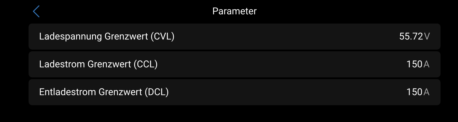
Momentan ist der Akku bei 71% 54,3V und er läd leider nur mit 36,4A(maximal 50A) und es wird ins 1382W ins Netz gedrückt. Normalerweise sollte er doch mit einem größeren Strom laden.
[DEFAULT]

; --------- Set logging level ---------
; ERROR: Only errors are logged
; WARNING: Errors and warnings are logged
; INFO: Errors, warnings and info messages are logged
; DEBUG: Errors, warnings, info and debug messages are logged
LOGGING = INFO


; --------- Battery Current limits ---------
MAX_BATTERY_CHARGE_CURRENT    = 60.0
MAX_BATTERY_DISCHARGE_CURRENT = 60.0


; --------- Cell Voltages ---------
; Description:
;     Cell min/max voltages which are used for:
;         - Calculating the min/max battery voltage
;         - Trigger the SoC reset when SoC calculation is enabled
; Example:
;     16 cells * 3.45 V/cell = 55.2 V max charge voltage.
;     16 cells * 2.90 V/cell = 46.4 V min discharge voltage
MIN_CELL_VOLTAGE   = 2.900
; Max voltage (can seen as absorption voltage)
MAX_CELL_VOLTAGE   = 3.450
; Float voltage (can be seen as resting voltage)
FLOAT_CELL_VOLTAGE = 3.375


; --------- SOC reset voltage (needs to match BMS settings) ---------
; +++ This has nothing to do with "SOC calculation" in a section below +++
; This is one of the possibilities to reset the SoC to 100%, because of SoC drift.
; Description:
;     May be needed to reset the SoC to 100% once in a while for some BMS, because of SoC drift.
;     Some BMS may needed to reset the SoC to 100% once in a while, because of SoC drift. Some
;     devices, like JKBMS, will reset their internal SOC value, if they reach the upper voltage level.
;     Using this method, the charging voltage can be raised regularly to achieve that.
;     (other BMS like Daly need an active overwriting of the SOC parameter. This happens each time when
;     the charging mode changes from Bulk/Absorption to float (and the cells are equalised). They do
;     not need this feature here.)
;     Specify the cell voltage where the SoC should be reset to 100% by the BMS.
;       - JKBMS: SoC is reset to 100% if one cell reaches OVP (over voltage protection) voltage
;     As you have to adopt this value to your system, I recommend to start with
;     OVP voltage - 0.030 (see Example).
;       - Try to increase (add) by 0.005 in steps, if the system does not switch to float mode, even if
;         the target voltage SOC_RESET_VOLTAGE * CELL_COUNT is reached.
;       - Try to decrease (lower) by 0.005 in steps, if the system hits the OVP too fast, before all
;         cells could be balanced and the system goes into protection mode multiple times.
; Example:
;     If OVP is 3.650, then start with 3.620 and increase/decrease by 0.005
; Note:
;     The value has to be higher as the MAX_CELL_VOLTAGE
;     You also have to set CELL_VOLTAGES_WHILE_CHARGING accordingly, if you set CCCM_CV_ENABLE to true
;         else the charging current will be reduced to 0 before the target voltage is reached and the
;         battery will never switch to float
SOC_RESET_VOLTAGE = 3.650
; Specify after how many days the SOC reset voltage should be reached again
; The timer is reset when the SOC reset voltage is reached
; Leave empty if you don't want to use the SOC reset feature
; Example:
;     Value is set to 15
;     day 1: SOC reset reached once
;     day 16: SOC reset reached twice
;     day 31: SOC reset not reached since it's very cloudy
;     day 34: SOC reset reached since the sun came out
;     day 49: SOC reset reached again, since last time it took 3 days to reach SOC reset voltage
SOC_RESET_AFTER_DAYS =


; --------- SOC calculation ---------
; +++ This has nothing to do with "SOC reset voltage" in a section above +++
; This is one of the possibilities to reset the SoC to 100%, because of SoC drift.
; Description:
;     Calculate the SOC in the driver. Do not use the SOC reported by the BMS
; SOC_CALCULATION:
;     True: Calc SOC in the driver, do not use SOC reported from BMS
;         - The SOC is calculated by integration of the current reported
;         - The current reported can be corrected by the map
;           (SOC_CALC_CURRENT_REPORTED_BY_BMS, SOC_CALC_CURRENT_MEASURED_BY_USER)
;         - The SOC is set to 100% if the following conditions apply for at least SOC_RESET_TIME seconds:
;             * Highest cell voltage is higher or equal to MAX_CELL_VOLTAGE
;             * Current is lower than SOC_RESET_CURRENT
;         - The SOC is set to 0% if the following conditions apply for at least SOC_RESET_TIME seconds:
;             * Lowest cell voltage is lower or equal to MIN_CELL_VOLTAGE
;             * Battery is discharging
;         - The calculated SOC is stored in dbus to persist a driver restart
;     False: Use SOC reported from BMS (none of the other parameters apply)
; More info: https://github.com/Louisvdw/dbus-serialbattery/pull/868
SOC_CALCULATION   = False
SOC_RESET_CURRENT = 7
SOC_RESET_TIME    = 60
SOC_CALC_CURRENT_REPORTED_BY_BMS  = -300, 300
SOC_CALC_CURRENT_MEASURED_BY_USER = -300, 300
; Example to set small currents to zero
;     SOC_CALC_CURRENT_REPORTED_BY_BMS  = -300, -0.5, 0.5, 300
;     SOC_CALC_CURRENT_MEASURED_BY_USER = -300,    0,   0, 300


; --------- Bluetooth BMS ---------
; Description:
;     Specify the Bluetooth BMS and it's MAC address that you want to install. Leave empty to disable
; Available Bluetooth BMS:
;     Jkbms_Ble, LltJbd_Ble
; Example for one BMS:
;     BLUETOOTH_BMS = Jkbms_Ble C8:47:8C:00:00:00
; Example for multiple BMS:
;     BLUETOOTH_BMS = Jkbms_Ble C8:47:8C:00:00:00, Jkbms_Ble C8:47:8C:00:00:11, Jkbms_Ble C8:47:8C:00:00:22
BLUETOOTH_BMS =


; --------- Bluetooth use USB ---------
; Description:
;     Some users reported issues to the built in bluetooth module, you can try to fix it with an USB
;     module. After a change you have to run reinstall-local.sh and to manual reboot the device!
;     The usb bluetooth module must have BLE support (bluetooth version >= 4.0)
;     Other bluetooth devices such as Ruuvi tags not tested yet.
; False: Use the built in bluetooth module
; True: Disable built in bluetooth module and try to use USB module
BLUETOOTH_USE_USB = False


; --------- CAN BMS ---------
; Description:
;     Specify the CAN port(s) where the BMS is connected to. Leave empty to disable
; Available CAN BMS:
;     Daly_Can, Jkbms_Can
; Example for one CAN port:
;     CAN_PORT = can0
; Example for multiple CAN ports:
;     CAN_PORT = can0, can8, can9
CAN_PORT =


; --------- BMS disconnect behaviour ---------
; Description:
;     Block charge and discharge when the communication to the BMS is lost. If you are removing the
;     BMS on purpose, then you have to restart the driver/system to reset the block.
; False:
;     Charge and discharge is not blocked on BMS communication loss for 20 minutes, if cell voltages are between
;     3.25 V and 3.35 V. Else the driver block charge and discharge after 60 seconds.
; True:
;     Charge and discharge is blocked on BMS communication loss, it's unblocked when connection is established
;     again or the driver/system is restarted. This is the Victron Energy default behaviour.
BLOCK_ON_DISCONNECT = False


; --------- Charge mode ---------
; Choose the mode for voltage / current limitations (True / False)
; False is a step mode: This is the default with limitations on hard boundary steps
; True is a linear mode:
;     For CCL and DCL the values between the steps are calculated for smoother values
;     For CVL max battery voltage is calculated dynamically in order that the max cell voltage is not exceeded
LINEAR_LIMITATION_ENABLE = True

; Specify in seconds how often the linear values should be recalculated
LINEAR_RECALCULATION_EVERY = 60
; Specify in percent when the linear values should be recalculated immediately
; Example:
;     10 for a immediate change, when the value changes by more than 10%
LINEAR_RECALCULATION_ON_PERC_CHANGE = 33


; --------- External current sensor ---------
; Specify the dbus device and path where the external current sensor is connected to
; You can find it by executing the dbus-spy command
; Example for a external current sensor connected to the VE.Bus port:
;     EXTERNAL_CURRENT_SENSOR_DBUS_DEVICE = com.victronenergy.vebus.ttyS3
;     EXTERNAL_CURRENT_SENSOR_DBUS_PATH = /Dc/0/Current
EXTERNAL_CURRENT_SENSOR_DBUS_DEVICE =
EXTERNAL_CURRENT_SENSOR_DBUS_PATH =


; --------- Charge Voltage limitation (affecting CVL) ---------
; Description:
;     Limit max charging voltage (MAX_CELL_VOLTAGE * cell count), switch from max voltage to float
;     voltage (FLOAT_CELL_VOLTAGE * cell count) and back
;     False: Max charging voltage is always kept
;     True: Max charging voltage is reduced based on charge mode
;         Step mode: After max voltage is reached for MAX_VOLTAGE_TIME_SEC it switches to float voltage. After
;             SoC is below SOC_LEVEL_TO_RESET_VOLTAGE_LIMIT it switches back to max voltage.
;         Linear mode: After max voltage is reached and cell voltage difference is smaller or equal to
;             CELL_VOLTAGE_DIFF_KEEP_MAX_VOLTAGE_UNTIL it switches to float voltage after MAX_VOLTAGE_TIME_SEC
;             additional seconds.
;             After cell voltage difference is greater or equal to CELL_VOLTAGE_DIFF_TO_RESET_VOLTAGE_LIMIT
;             OR
;             SoC is below SOC_LEVEL_TO_RESET_VOLTAGE_LIMIT
;             it switches back to max voltage.
; Example when set to True:
;     Step mode:
;          The battery reached max voltage of 55.2 V and hold it for 900 seconds, the the CVL is switched to
;          float voltage of 53.6 V to don't stress the batteries. Allow max voltage of 55.2 V again, if SoC is
;          once below 80%
;     Linear mode:
;          The battery reached max voltage of 55.2 V and the max cell difference is 0.010 V, then switch to float
;          voltage of 53.6 V after 900 additional seconds to don't stress the batteries. Allow max voltage of
;          55.2 V again if max cell difference is above 0.080 V or SoC below 80%.
; Charge voltage control management enable (True/False).
CVCM_ENABLE = True

; -- CVL reset based on cell voltage diff (linear mode)
; Specify cell voltage diff where CVL limit is kept until diff is equal or lower
CELL_VOLTAGE_DIFF_KEEP_MAX_VOLTAGE_UNTIL        = 0.010
; Specify cell voltage diff where MAX_VOLTAGE_TIME_SEC restarts if diff is bigger
CELL_VOLTAGE_DIFF_KEEP_MAX_VOLTAGE_TIME_RESTART = 0.013
; Specify cell voltage diff where CVL limit is reset to max voltage, if value get above
; the cells are considered as imbalanced, if the cell diff exceeds 5% of the nominal cell voltage
; e.g. 3.2 V * 5 / 100 = 0.160 V
CELL_VOLTAGE_DIFF_TO_RESET_VOLTAGE_LIMIT        = 0.080

; -- CVL reset based on SoC option (step mode & linear mode)
; Specify how long the max voltage should be kept
;     Step mode: If reached then switch to float voltage
;     Linear mode: If cells are balanced keep max voltage for further MAX_VOLTAGE_TIME_SEC seconds
MAX_VOLTAGE_TIME_SEC = 900
; Specify SoC where CVL limit is reset to max voltage
;     Step mode: If SoC gets below
;     Linear mode: If cells are unbalanced or if SoC gets below
SOC_LEVEL_TO_RESET_VOLTAGE_LIMIT = 80


; --------- Cell Voltage Current limitation (affecting CCL/DCL) ---------
; Description: Maximal charge / discharge current will be in-/decreased depending on min and max cell voltages
; Example:
;     18 cells * 3.55 V/cell = 63.9 V max charge voltage
;     18 cells * 2.70 V/cell = 48.6 V min discharge voltage
;     But in reality not all cells reach the same voltage at the same time. The (dis)charge current
;     will be (in-/)decreased, if even ONE SINGLE BATTERY CELL reaches the limits

; Charge current control management referring to cell-voltage enable (True/False).
CCCM_CV_ENABLE = True
; Discharge current control management referring to cell-voltage enable (True/False).
DCCM_CV_ENABLE = True

; Set steps to reduce battery current
; The current will be changed linear between those steps if LINEAR_LIMITATION_ENABLE is set to True
CELL_VOLTAGES_WHILE_CHARGING      = 3.55, 3.50, 3.45, 3.30
MAX_CHARGE_CURRENT_CV_FRACTION    =    0, 0.05,  0.7,    1

CELL_VOLTAGES_WHILE_DISCHARGING   = 2.70, 2.80, 2.90, 3.10
MAX_DISCHARGE_CURRENT_CV_FRACTION =    0,  0.1,  0.5,    1


; --------- Cell Voltage limitation (affecting CVL) ---------
; This function prevents a bad balanced battery to overcharge the cell with the highest voltage and the bms to
; switch off because of overvoltage of this cell.
;
; Example:
;     15 cells are at 3.4v, 1 cell is at 3.6v. Total voltage of battery is 54.6v and the Victron System sees no reason to
;     lower the charging current as the control_voltage (Absorption Voltage) is 55.2v
;     In this case the Cell Voltage limitation kicks in and lowers the control_voltage to keep it close to the MAX_CELL_VOLTAGE.
;
; In theory this can also be done with CCL, but doing it with CVL has 2 advantages:
;     - In a well balanced system the current can be kept quite high till the end of charge by using MAX_CELL_VOLTAGE for charging.
;     - In systems with MPPTs and DC-feed-in activated the Victron systems do not respect CCL, so CVL is the only way to prevent the
;       highest cell in a bad balanced system from overcharging.
;
; There are 2 methods implemented to calculate CVL:
;   1. penalty_sum-Method (CVL_ICONTROLLER_MODE = False)
;      The voltage-overshoot of all cells that exceed MAX_CELL_VOLTAGE is summed up and the control voltage is lowered by this "penalty_sum".
;      This is calculated every LINEAR_RECALCULATION_EVERY seconds.
;      In fact, this is a P-Controller.
;   2. I-Controller (CVL_ICONTROLLER_MODE = True)
;      An I-Controller tries to control the voltage of the highest cell to MAX_CELL_VOLTAGE + CELL_VOLTAGE_DIFF_KEEP_MAX_VOLTAGE_UNTIL.
;      (for example 3.45 V + 0.01 V = 3.46 V). If the voltage of the highest cell is above this level, CVL is reduced. If the voltage is below, CVL is
;      increased until cellcount*MAX_CELL_VOLTAGE.
;      An I-Part of 0.2 V/Vs (CVL_ICONTROLLER_FACTOR) has proved to be a stable and fast controlling-behaviour.
;      This method is not as fast as the penalty_sum-Method but usually smoother and more stable against toggling and has no stationary deviation.
; More info: https://github.com/Louisvdw/dbus-serialbattery/pull/882
CVL_ICONTROLLER_MODE   = False
CVL_ICONTROLLER_FACTOR = 0.2


; --------- Temperature limitation (affecting CCL/DCL) ---------
; Description:
;     Maximal charge / discharge current will be in-/decreased depending on temperatures
;     NOTE: The temperatures are in ° Celsius. Temperature sensor 1 to 4 are used for the calculation.
; Example:
;     The temperature limit will be monitored to control the currents. If there are two temperature sensors,
;     then the worst case will be calculated and the more secure lower current will be set.
; Charge current control management referring to temperature enable (True/False).
CCCM_T_ENABLE = True
; Discharge current control management referring to temperature enable (True/False).
DCCM_T_ENABLE = True

; Set steps to reduce battery current
; The current will be changed linear between those steps if LINEAR_LIMITATION_ENABLE is set to True
TEMPERATURES_WHILE_CHARGING      =    0,    2,    5,   10,   15,   20,   35,   40,   55
MAX_CHARGE_CURRENT_T_FRACTION    = 0.00, 0.10, 0.20, 0.40, 0.80, 1.00, 1.00, 0.40, 0.00

TEMPERATURES_WHILE_DISCHARGING   =  -20,    0,    5,   10,   15,   45,   55
MAX_DISCHARGE_CURRENT_T_FRACTION = 0.00, 0.20, 0.30, 0.40, 1.00, 1.00, 0.00


; --------- SOC limitation (affecting CCL/DCL) ---------
; Description:
;     Maximal charge / discharge current will be increased / decreased depending on State of Charge
;     Since the SoC is not as accurate as the cell voltage, this option is disabled by default
; Example:
;     The SoC limit will be monitored to control the currents.
; Charge current control management referring to SoC enable (True/False).
CCCM_SOC_ENABLE = False
; Discharge current control management referring to SoC enable (True/False).
DCCM_SOC_ENABLE = False

; Set steps to reduce battery current
; The current will be changed linear between those steps if LINEAR_LIMITATION_ENABLE is set to True
SOC_WHILE_CHARGING                 =   98,   95,   90,   85
MAX_CHARGE_CURRENT_SOC_FRACTION    = 0.10, 0.20, 0.50, 1.00

SOC_WHILE_DISCHARGING              =    5,   10,   15,   20
MAX_DISCHARGE_CURRENT_SOC_FRACTION = 0.10, 0.20, 0.50, 1.00


; --------- Time-To-Go ---------
; Description:
;     Calculates the time to go shown in the GUI
;     Recalculation is done based on TIME_TO_SOC_RECALCULATE_EVERY
TIME_TO_GO_ENABLE = True


; --------- Time-To-Soc ---------
; Description:
;     Calculates the time to a specific SoC
; Example:
;     TIME_TO_SOC_POINTS = 50, 25, 15, 0
;     6h 24m remaining until 50% SoC
;     17h 36m remaining until 25% SoC
;     22h 5m remaining until 15% SoC
;     28h 48m remaining until 0% SoC
; Set of SoC percentages to report on dbus and MQTT. The more you specify the more it will impact system performance.
; [Valid values 0-100, comma separated list. More that 20 intervals are not recommended]
; Example: TIME_TO_SOC_POINTS = 100, 95, 90, 85, 75, 50, 25, 20, 10, 0
; Leave empty to disable
TIME_TO_SOC_POINTS =
; Specify TimeToSoc value type [Valid values 1, 2, 3]
; 1 Seconds
; 2 Time string <days>d <hours>h <minutes>m <seconds>s
; 3 Both seconds and time string "<seconds> [<days>d <hours>h <minutes>m <seconds>s]"
TIME_TO_SOC_VALUE_TYPE = 1
; Specify in seconds how often the TimeToSoc should be recalculated
; Minimum are 5 seconds to prevent CPU overload
TIME_TO_SOC_RECALCULATE_EVERY = 60
; Include TimeToSoC points when moving away from the SoC point [Valid values True, False]
; These will be as negative time. Disabling this improves performance slightly
TIME_TO_SOC_INC_FROM = False


; --------- Additional settings ---------
; Specify one or more BMS types to load else leave empty to try to load all available
; Available BMS:
;     Daly, Ecs, EG4_Lifepower, EG4_LL, HeltecModbus, HLPdataBMS4S, Jkbms, Jkbms_pb, LltJbd, Renogy, Seplos
; Available BMS, but disabled by default (just enter one or more below and it will be enabled):
;     ANT, MNB, Sinowealth
BMS_TYPE =

; Exclude this serial devices from the driver startup
; Example:
;     /dev/ttyUSB2, /dev/ttyUSB4
EXCLUDED_DEVICES =

; BMS poll interval in seconds
; If the driver consumes to much CPU, you can increase this value to reduce refresh rate
; and CPU usage
; Default for most BMS is 1 second, some BMS may have a higher value
; Leave empty to use the BMS default value, decimal values are allowed
POLL_INTERVAL =

; Auto reset SoC
; If on, then SoC is reset to 100%, if the value switches from absorption to float voltage
; Currently only working for Daly BMS and JKBMS BLE
AUTO_RESET_SOC = True

; Publish the config settings to the dbus path "/Info/Config/"
PUBLISH_CONFIG_VALUES = False

; Select the format of cell data presented on dbus [Valid values 0,1,2,3]
; 0 Do not publish all the cells (only the min/max cell data as used by the default GX)
; 1 Format: /Voltages/Cell (also available for display on Remote Console)
; 2 Format: /Cell/#/Volts
; 3 Both formats 1 and 2
BATTERY_CELL_DATA_FORMAT = 1

; Simulate Midpoint graph (True/False).
MIDPOINT_ENABLE = False

; Battery temperature
; Specify how the battery temperature is assembled
; 0 Get mean of temperature sensor 1 to sensor 4
; 1 Get only temperature from temperature sensor 1
; 2 Get only temperature from temperature sensor 2
; 3 Get only temperature from temperature sensor 3
; 4 Get only temperature from temperature sensor 4
TEMP_BATTERY = 0

; Temperature sensor 1 name
TEMP_1_NAME = Temp 1

; Temperature sensor 2 name
TEMP_2_NAME = Temp 2

; Temperature sensor 2 name
TEMP_3_NAME = Temp 3

; Temperature sensor 2 name
TEMP_4_NAME = Temp 4

; Show additional info in GUI -> Serialbattery -> Parameters
; This will show additional information to better understand how the driver works
; and what values are currently set which are not shown elsewhere in the GUI
; You have to scroll down to see the additional information
GUI_PARAMETERS_SHOW_ADDITIONAL_INFO = False


; --------- BMS specific settings ---------

; -- Unique ID settings
; Some already assembled BMS have no unique ID and no possibility to set one. In this case
; you can use the USB port as the unique ID.
; It may be possible that VRM ID's and custom names are not saved/restored correctly in this case.
USE_PORT_AS_UNIQUE_ID = False

; -- LltJbd settings
; SoC low levels
; Note:
;     SOC_LOW_WARNING is also used to calculate the Time-To-Go even if you are not using a LltJbd BMS
SOC_LOW_WARNING = 20
SOC_LOW_ALARM   = 10

; -- Daly settings
; Battery capacity (amps), if the BMS does not support reading it
BATTERY_CAPACITY = 50
; Invert Battery Current. Default non-inverted. Set to -1 to invert
INVERT_CURRENT_MEASUREMENT = 1

; -- JKBMS settings
; Predefines cell count for Jkbms_can
; The cell count should be auto-detected by identifying the highest cell number,
; but this process may be sometimes slow what could cause that cells voltage is not not
; updated in VenusOS. Try this workaround if you experience problems with cell voltage.
JKBMS_CAN_CELL_COUNT = 1

; -- ESC GreenMeter and Lipro device settings
GREENMETER_ADDRESS  = 1
LIPRO_START_ADDRESS = 2
LIPRO_END_ADDRESS   = 4
LIPRO_CELL_COUNT    = 15

; -- HeltecModbus (Heltec SmartBMS/YYBMS) settings
; Set the Modbus addresses from the adapters
; Separate each address to check by a comma like: 1, 2, 3, ...
; factory default address will be 1
HELTEC_MODBUS_ADDR = 1

; -- Seplos V3 settings
; Use min/max cell voltage, CVL, CCL and DCL from the BMS
SEPLOS_USE_BMS_VALUES = False


; --------- Voltage drop ---------
; If you have a voltage drop between the BMS and the charger because of wire size or length
; then you can specify the voltage drop here. The driver will then add the voltage drop
; to the calculated CVL to compensate.
; Example:
;     cell count: 16
;     MAX_CELL_VOLTAGE = 3.45
;     max voltage calculated = 16 * 3.45 = 55.20
;     CVL is set to 55.20 V and the battery is now charged until the charger reaches 55.20 V.
;     The BMS now measures 55.05 V since there is a voltage drop of 0.15 V on the cable.
;     Since the dbus-serialbattery reads the voltage of 55.05 V from the BMS the max voltage
;     of 55.20 V is never reached and max voltage is kept forever.
;     By setting the VOLTAGE_DROP to 0.15 V the voltage on the charger is increased and the
;     target voltage on the BMS is reached.
VOLTAGE_DROP = 0.00