Hallo zusammen, auch auf die Gefahr hin dass ich einen Rüffel für ein Doppelposting bekomme weil ich die Frage an ander Stelle bereits in ähnlicher Form gestellt habe, aber das Thema wurmt mich und ich komme irgendwie nicht weiter.
Irgendwie werden sämtliche Einstellungen die ich in der utils.py vorgenommen habe völlig ignoriert oder ich hab einfach noch etwas übersehen.
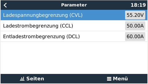
Das System besteht aus einem MP2 3000, einem MPPT150/45 sowie einem 16S 105Ah DIY Akku der mit einem JK BMS ausgerüstet ist. Ein Initalladen und TOP Balancing habe ich vor einiger Zeit schon durchgeführt. Der MPPT lädt (aktuell im Testbetrieb mit einem Labornetzteil) wie er soll. Aber ich bekomme aus irgendwelchen Gründen weder CVL auf meinen gewünschten Wert, noch kann ich den max. Entladestrom auf die gewünschten 75A erhöhen.
Anbei meine utils.py eventuell kann mir jemand auf die Sprünge helfen warum meine Änderungen in der utils.py vom VenusOS ignoriert werden?
# Choose the mode for voltage / current limitations (True / False)
# False is a Step mode. This is the default with limitations on hard boundary steps
# True "Linear" # New linear limitations by WaldemarFech for smoother values
LINEAR_LIMITATION_ENABLE = False
######### Cell Voltage limitation #########
# Description:
# Maximal charge / discharge current will be in-/decreased depending on min- and max-cell-voltages
# Example: 18cells * 3.55V/cell = 63.9V max charge voltage. 18 * 2.7V = 48,6V min discharge voltage
# ... but the (dis)charge current will be (in-/)decreased, if even ONE SINGLE BATTERY CELL reaches the limits
# Charge current control management referring to cell-voltage enable (True/False).
CCCM_CV_ENABLE = True
# Discharge current control management referring to cell-voltage enable (True/False).
DCCM_CV_ENABLE = True
# Set Steps to reduce battery current. The current will be changed linear between those steps
CELL_VOLTAGES_WHILE_CHARGING = [3.65, 3.55, 3.50, 3.45] #[3.55, 3.50, 3.45, 3.30]
MAX_CHARGE_CURRENT_CV = [ 0, 2, 30, 50] #[ 0, 2, 30, 50]
CELL_VOLTAGES_WHILE_DISCHARGING = [2.50, 2.60, 2.80, 3.00] #[2.70, 2.80, 2.90, 3.10]
MAX_DISCHARGE_CURRENT_CV = [ 0, 5, 30, 75] #[ 0, 5, 30, 75]
######### Temperature limitation #########
# Description:
# Maximal charge / discharge current will be in-/decreased depending on temperature
# Example: The temperature limit will be monitored to control the currents. If there are two temperature senors,
# then the worst case will be calculated and the more secure lower current will be set.
# Charge current control management referring to temperature enable (True/False).
CCCM_T_ENABLE = True
# Charge current control management referring to temperature enable (True/False).
DCCM_T_ENABLE = True
# Set Steps to reduce battery current. The current will be changed linear between those steps
TEMPERATURE_LIMITS_WHILE_CHARGING = [55, 40, 35, 5, 2, 0]
MAX_CHARGE_CURRENT_T = [ 0, 28, 50, 50, 28, 0]
TEMPERATURE_LIMITS_WHILE_DISCHARGING = [55, 40, 35, 5, 0, -20]
MAX_DISCHARGE_CURRENT_T = [ 0, 28, 75, 75, 28, 0]
# if the cell voltage reaches 3.55V, then reduce current battery-voltage by 0.01V
# if the cell voltage goes over 3.6V, then the maximum penalty will not be exceeded
# there will be a sum of all penalties for each cell, which exceeds the limits
PENALTY_AT_CELL_VOLTAGE = [3.45, 3.55, 3.6]
PENALTY_BATTERY_VOLTAGE = [0.01, 1.0, 2.0] # this voltage will be subtracted
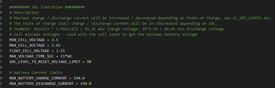
######### SOC limitation #########
# Description:
# Maximal charge / discharge current will be increased / decreased depending on State of Charge, see CC_SOC_LIMIT1 etc.
# The State of Charge (SoC) charge / discharge current will be in-/decreased depending on SOC.
# Example: 16cells * 3.45V/cell = 55,2V max charge voltage. 16*2.9V = 46,4V min discharge voltage
# Cell min/max voltages - used with the cell count to get the min/max battery voltage
MIN_CELL_VOLTAGE = 2.80
MAX_CELL_VOLTAGE = 3.60
FLOAT_CELL_VOLTAGE = 3.35
MAX_VOLTAGE_TIME_SEC = 15*60
SOC_LEVEL_TO_RESET_VOLTAGE_LIMIT = 90
# battery Current limits
MAX_BATTERY_CHARGE_CURRENT = 50.0
MAX_BATTERY_DISCHARGE_CURRENT = 75.0
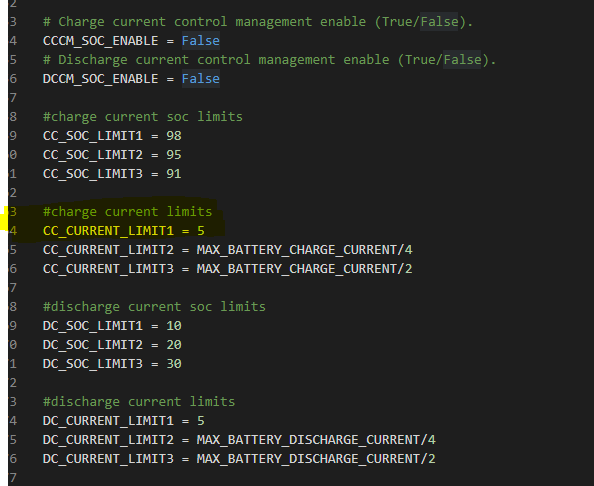
# Charge current control management enable (True/False).
CCCM_SOC_ENABLE = False
# Discharge current control management enable (True/False).
DCCM_SOC_ENABLE = False
#charge current soc limits
CC_SOC_LIMIT1 = 98
CC_SOC_LIMIT2 = 95
CC_SOC_LIMIT3 = 91
#charge current limits
CC_CURRENT_LIMIT1 = 5
CC_CURRENT_LIMIT2 = MAX_BATTERY_CHARGE_CURRENT/4
CC_CURRENT_LIMIT3 = MAX_BATTERY_CHARGE_CURRENT/2
#discharge current soc limits
DC_SOC_LIMIT1 = 10
DC_SOC_LIMIT2 = 20
DC_SOC_LIMIT3 = 30
#discharge current limits
DC_CURRENT_LIMIT1 = 5
DC_CURRENT_LIMIT2 = MAX_BATTERY_DISCHARGE_CURRENT/4
DC_CURRENT_LIMIT3 = MAX_BATTERY_DISCHARGE_CURRENT/2
# Charge voltage control management enable (True/False).
CVCM_ENABLE = True
# Simulate Midpoint graph (True/False).
MIDPOINT_ENABLE = False
#soc low levels
SOC_LOW_WARNING = 20
SOC_LOW_ALARM = 10
# Daly settings
# Battery capacity (amps) if the BMS does not support reading it
BATTERY_CAPACITY = 105
# Invert Battery Current. Default non-inverted. Set to -1 to invert
INVERT_CURRENT_MEASUREMENT = 1
# TIME TO SOC settings [Valid values 0-100, but I don't recommend more that 20 intervals]
# Set of SoC percentages to report on dbus. The more you specify the more it will impact system performance.
# TIME_TO_SOC_POINTS = [100, 95, 90, 85, 80, 75, 70, 65, 60, 55, 50, 45, 40, 35, 30, 25, 20, 15, 10, 5, 0] # Every 5% SoC
# TIME_TO_SOC_POINTS = [100, 95, 90, 85, 75, 50, 25, 20, 10, 0]
TIME_TO_SOC_POINTS = [] # No data set to disable
# Specify TimeToSoc value type: [Valid values 1,2,3]
# TIME_TO_SOC_VALUE_TYPE = 1 # Seconds
# TIME_TO_SOC_VALUE_TYPE = 2 # Time string HH:MN:SC
TIME_TO_SOC_VALUE_TYPE = 3 # Both Seconds and time str "<seconds> [days, HR:MN:SC]"
# Specify how many loop cycles between each TimeToSoc updates
TIME_TO_SOC_LOOP_CYCLES = 5
# Include TimeToSoC points when moving away from the SoC point. [Valid values True,False]
# These will be as negative time. Disabling this improves performance slightly.
TIME_TO_SOC_INC_FROM = False
# Select the format of cell data presented on dbus. [Valid values 0,1,2,3]
# 0 Do not publish all the cells (only the min/max cell data as used by the default GX)
# 1 Format: /Voltages/Cell# (also available for display on Remote Console)
# 2 Format: /Cell/#/Volts
# 3 Both formats 1 and 2
BATTERY_CELL_DATA_FORMAT = 1
# Settings for ESC GreenMeter and Lipro devices
GREENMETER_ADDRESS = 1
LIPRO_START_ADDRESS = 2
LIPRO_END_ADDRESS = 4
LIPRO_CELL_COUNT = 15